Table of Contents
SH570R6
J-Series, R-Series (R4, R6)
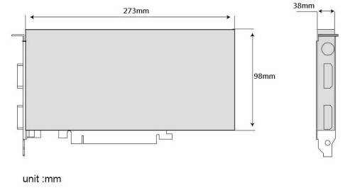
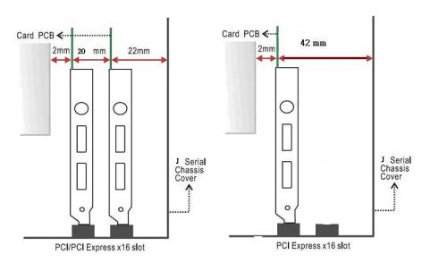
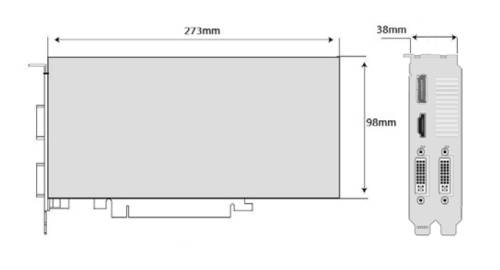
The maximum size of a card that fits in the J-Series is 273 mm (L) × 98 mm (H) × 38 mm (D). But due to the different layout designs of each model and VGA card, we strongly suggest to check our VGA support list for each model or test before purchasing the VGA card.
TPM/MAC address update
This update has two features:
- If the installation of Windows 11 cannot be completed because errors such as “The PC must support TPM 2.0” are displayed, please perform the following steps.
- If the MAC addresses of the network cards soldered on the mainboard are incorrectly formatted or not accepted by the operating system, please perform the following steps.
Please follow the steps in this exact order and do not skip any steps.
Re-Flash BIOS
- Re-Flash the BIOS v1.05 (or later if available) by USB drive (even if 1.05 is already installed): Download BIOS
- After BIOS flash, please clear the CMOS via “Clear CMOS & power button (SW1)”
- Disconnect the machine from power and shortcut the bottom pins (1 + 3) on the backside for at least 60 seconds with a screwdriver, jumper or another metal part.
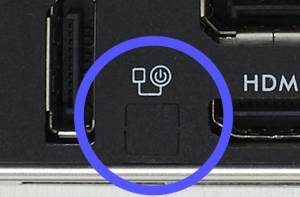
- Pinout:
- NOTE: The four pins may be covered. Please remove the plastic/mylar first.
- Now enter the BIOS again and press the following keys in order:
F3→ENTER→F4→ENTER - After that, please install and run Windows and check for MAC address:
- Please download and run the “MAC address update tool” in Windows 10/11: Download tool
How to use the MAC address update tool
- Get the update tool from here.
- Start the update.
- Unpack the contents of the ZIP archive.
- Run
sch_macupdate_x64.exe. It lists all available network adapters.
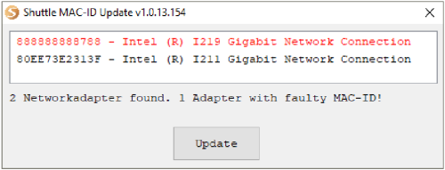
- A faulty adapter is marked red. To fix the MAC address (MAC-ID), click “Update”.
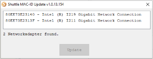
- After a few seconds, the update is done and all MAC addresses have been set to correct values again.
No network adapter found?
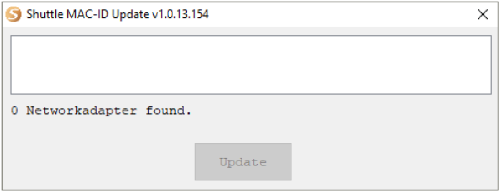
- If no network adapter is listed, close the tool.
- Execute
install.batbatch file from the same folder to a driver setup. - After finishing the driver installation, start
sch_macupdate_x64.exeagain.
Jumper settings and pinout
Fan connectors (FAN1, FAN2)
1=GND
2=+12V
3=FAN IO
4=FAN PWM
COM header (COM1)
1=DCD
2=RXD
3=TXD
4=DTR
5=GND
6=DSR
7=RTS
8=CTS
9=-XRI1
10=NULL
Clear CMOS, power button and +5V header (SW1)
1=RTC Reset
2=VCC_AUX
3=GND
4=Power SW