This is an old revision of the document!
NC03U
Upgrade the Shuttle NC03U WLAN module to WLN-M
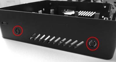
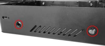
- Open the two NC03U covers from both sides.
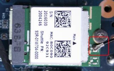
- Disconnect current WLAN antenna connector.
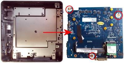
- Undo three screws and remove the mainboard out of the chassis.
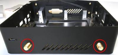
- Gently open the perforations for the WLAN antennas in the NC03U chassis.
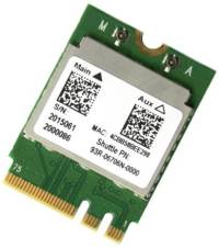
- Unpack the Shuttle WLN-M accessory.
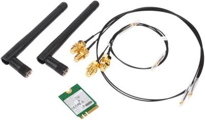
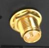
- Use the short cables (21 and 29 cm) from the WLN-M accessory. Put the SMA connectors of the antenna cables into the holes and fix them.

- Insert the mainboard again and fix it with three screws.
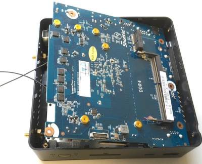
- Remove the currrent WLAN card. Insert the new WLAN card from the WLN-M accessory kit. Connect two antenna cables to the IPEX4 ports of the WLAN card.

- Install the chassis cover to the NC03U.
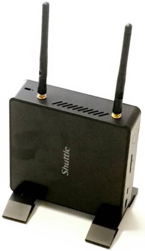
- Mount the two antennas to the SMA connectors - ready.
Quick Installation Guide
Begin Installation
The unit can be operated at an ambient temperature of max. 50°C (122°F).
Do not expose it to temperatures below 0°C (32°F) or above 50°C (122°F).
For safety reasons, please ensure that the power cord is disconnected before opening the case.
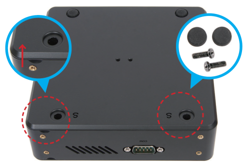
- Unscrew two screws of the back cover and remove it.
Memory Module Installation
This motherboard does only support 1.2V DDR4 memory modules.
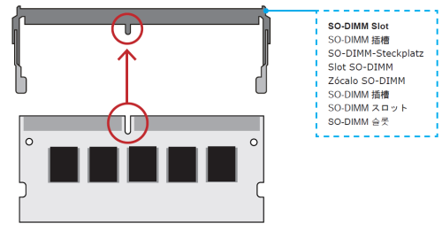
- Locate the SO-DIMM (DIMMB1) slot on the motherboard.
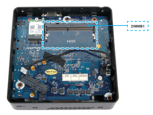
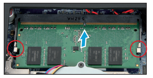
- Align the notch of the memory module with the one of the memory slot.
- Gently insert the memory module into the slot in a 45-degree angle.
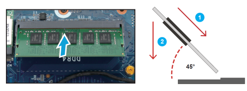
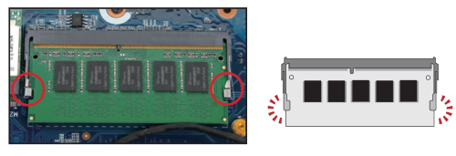
- Carefully push down the memory module until it snaps into the locking mechanism.
- If the DIMMA1 slot should also be equipped with a memory module, please proceed with the following steps.
- Turn your NC03U upside down and remove another cover.
- Locate the SO-DIMM (DIMMA1) slot on the motherboard.
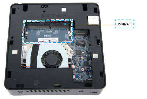
- Install the memory module into the DIMMA1 slot.
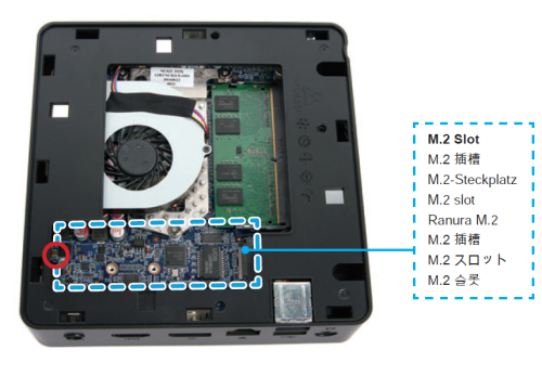
M.2 SSD Installation
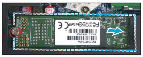
- Locate the M.2 slot on the motherboard and unfasten the screw first.
- Install the M.2 SSD into the M.2 slot and secure with a screw.
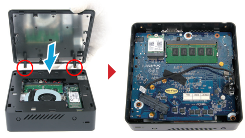
- Replace the cover and turn your NC03U upside down.
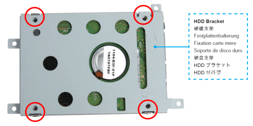
HDD Installation
This model supports 2.5“ SATA HDDs up to a thickness of 15mm.
- Mount the HDD into the bracket with four screws.
- Install the HDD with its bracket in the chassis with four screws and tear off the adhesive tape of the HDD cable.
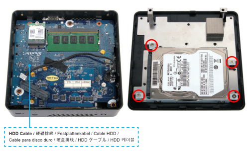
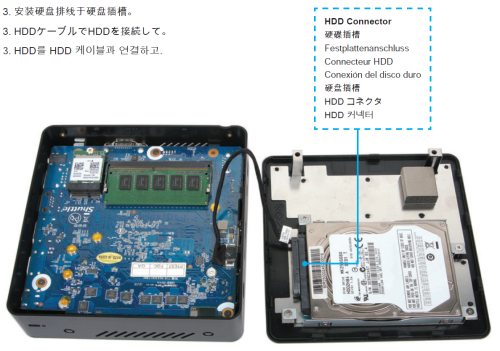
- Connect the HDD with HDD cable.
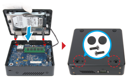
- Replace the cover and refasten the two screws.
Connecting to Power
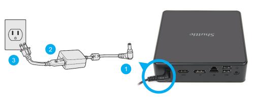
Please press the Del key while booting to enter BIOS. Here, please load the optimised BIOS settings.
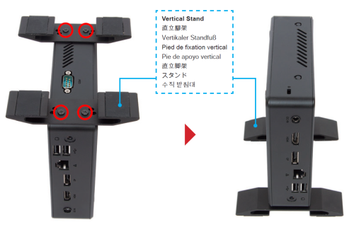
Using the Vertical Stand
- Install the vertical stand and check that it is properly aligned, then tighten securely with four screws.
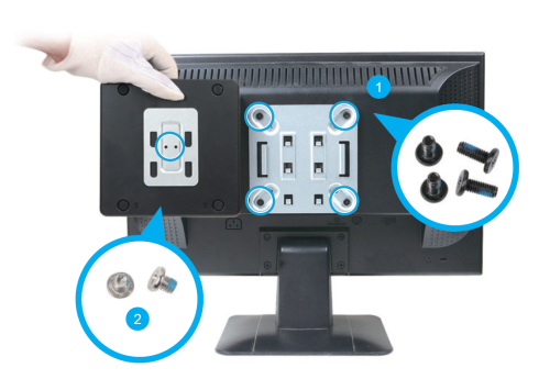
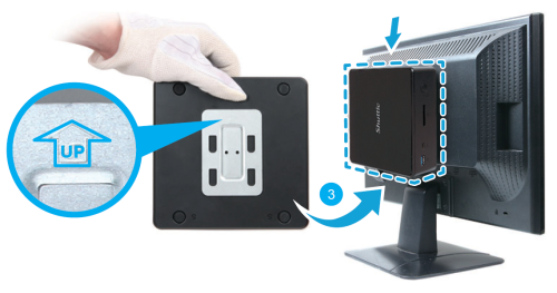
Installation of VESA Mount
Jumper settings and pinout
AC Back Auto Power ON
1=AMP(+)
2=GND
Clear CMOS
1=RTCRST
2=GND