This is an old revision of the document!
XH110G
What's the maximum permitted size an internal USB device may have?
The maximum permitted size is 11.5 x 28 x 88 mm.
What are the maximum dimensions a PCIe card may have?
The maximum permitted size for PCI-Express cards is 208.5 x 120 x 30 mm (LWH).
Quick Installation Guide
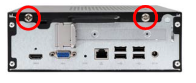
Begin Installation
- Unscrew the two thumbscrews of the chassis cover.
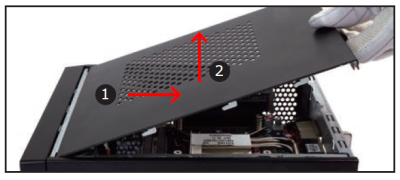
- Slide the cover backwards and upwards.
CPU/M.2 Card and ICE Module Installation
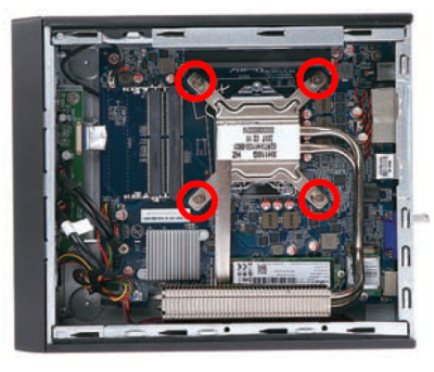
- Unfasten the four ICE module attachment screws.
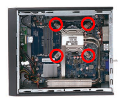
- Remove the ICE module from the chassis and put it aside.
This 1151-pin socket is fragile and easily damaged. Always use extreme care when installing a CPU and limit the number of times that you remove or change the CPU. Before installing the CPU, make sure to turn off the computer and unplug the power cord from the power outlet to prevent damage to the CPU.
→ Follow the steps below to correctly install the CPU into the motherboard CPU socket.
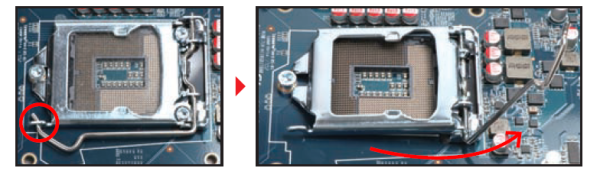
- First unlock and raise the socket lever.
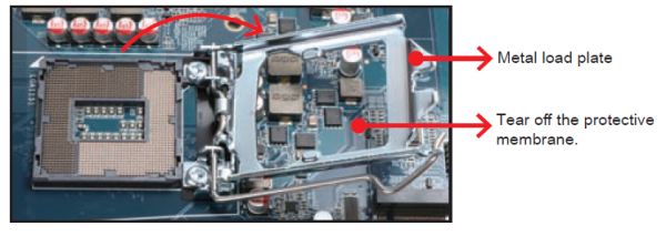
- Tear off the protective membrane from the metal load plate. Lift the metal load plate off the CPU socket.
DO NOT touch socket contacts. To protect the CPU socket, always replace the protective socket cover when the CPU is not installed.
- Orientate the CPU and socket, please align the CPU notches with the socket alignment keys. Make sure the CPU sits perfectly horizontal, then insert the CPU into the socket.
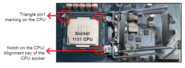
Please be aware of the CPU orientation, DO NOT force the CPU into the socket to avoid bending of pins on the socket and damage of CPU!
- Close the metal load plate, lower the CPU socket lever and lock in place.
- Spread thermal paste evenly on the CPU surface.
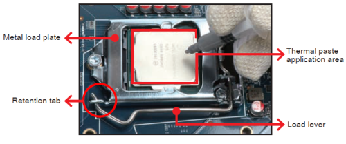
Please do not apply excess amount of thermal paste.
- As shown in Illustration.
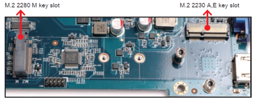
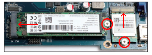
- Install the M.2 card into the M.2 slot and secure with the screw.
- Screw the ICE module to the mainboard.
Memory Module Installation
This motherboard does only support 1.2 V DDR4 SO-DIMM memory modules.
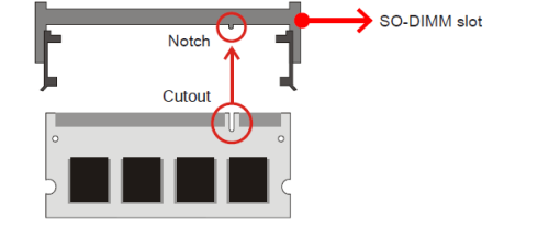
- Locate the SO-DIMM slot on the mainboard.
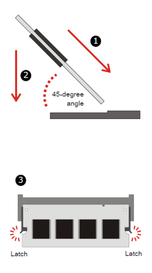
- Align the notch of the memory module with the one of the memory slot.
- Gently insert the module into the slot in a 45-degree angle.
- Carefully push down the memory module until it snaps into the locking mechanism.
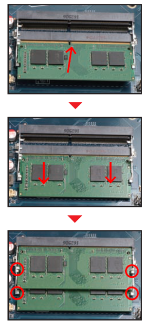
- Repeat the above steps to install additional memory modules, if required.
Installation of Expansion Card
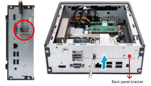
- Unfasten the expansion slot bracket screws. Remove the back panel bracket and put it aside.
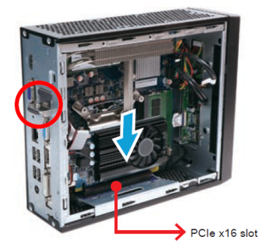
The maximum permitted size for display cards is 208.5 mm x 120 mm x 30 mm.
- Install the PCIe x16 card into the PCIe x16 slot.
- Secure the bracket.
HDD/SSD and USB Installation
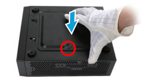
- Turn your XH110G upside down, then unscrew one screw of the HDD/SSD cover and remove it.
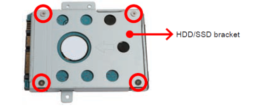
- Mount the HDD/SSD into the bracket with four screws.
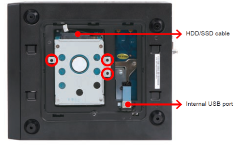
- Tear off the adhesive tape of the HDD cable. Install the HDD or SSD in the chassis using its bracket. Affix with three screws and connect the HDD or SSD with an HDD cable. Insert the USB drive, if required.
The maximum permitted size for an internal USB device is 11.5 mm x 28 mm x 88 mm.
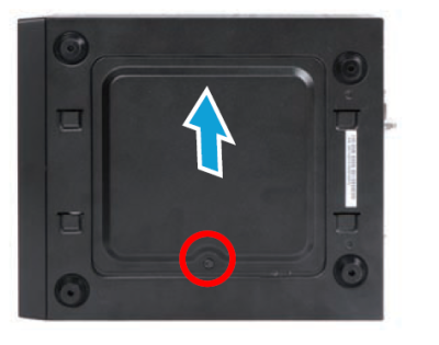
- Replace the HDD/SSD cover and turn your XH110G upside down.
- Replace the cover and refasten the thumbscrews.

- Complete.
Please press the “Del” key while booting to enter BIOS. Here, please load the optimized BIOS settings.
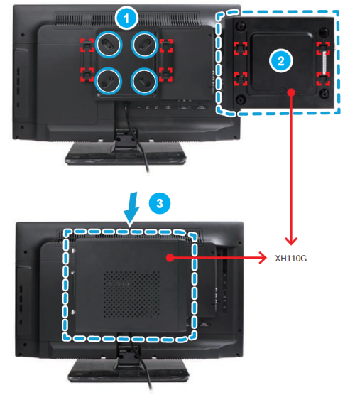
Installation of VESA Mount
Supports 75×75 mm and 100×100 mm VESA standard.