This is an old revision of the document!
P20U
Quick Installation Guide
Begin Installation
For safety reasons, please ensure that the power cord is disconnected before opening the case.
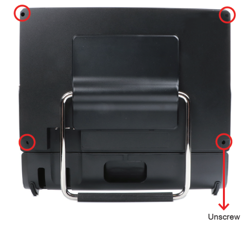
- Unscrew four screws of the back cover.
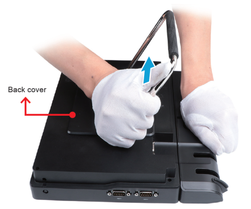
- Pull the back cover upward and remove it.
HDD or SSD Installation
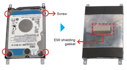
- Place an HDD or SSD in the rack and secure with the four screws from the sides. Affix the EMI shielding gasket with the adhesive tape, as shown.
- Tear off the adhesive tape of the serial ATA and power cable.
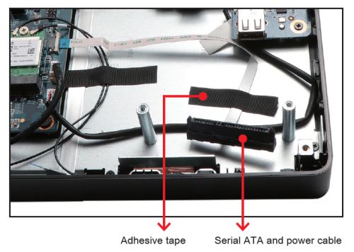
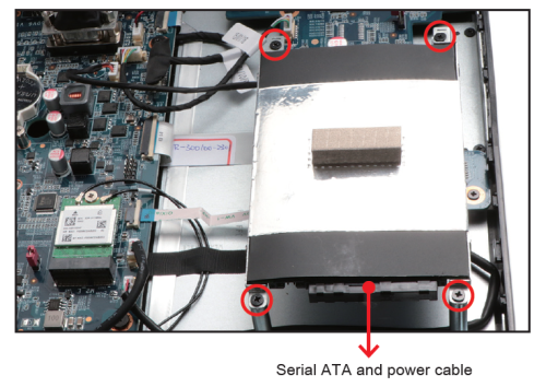
- Connect the Serial ATA and power cable to the HDD or SSD. Slide the rack into the chassis and refasten the screws.
Memory Module Installation
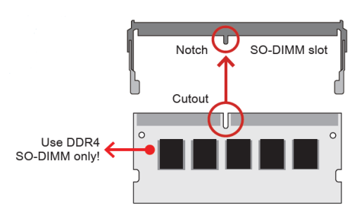
This mainboard does only support 1.2 V DDR4 SO-DIMM memory modules.
- Locate the SO-DIMM slot on the mainboard.
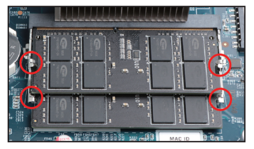
- Align the notch of the memory module with the one of the memory slot.
- Gently insert the module into the slot in a 45-degree angle.
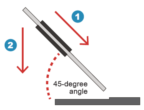
- Carefully push down the memory module until it snaps into the locking mechanism.
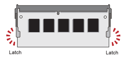
- Repeat the above steps to install additional memory modules, if required.
Component Installation
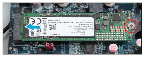
- As shown, unfasten the screw first.
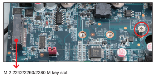
- Install the M.2 device into the M.2 slot and secure with the screw.
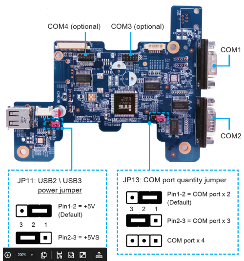
Daughter board (CM008)
Complete
- Replace the back cover and refasten the screws.
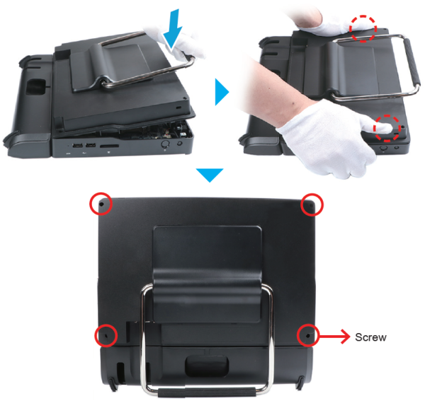
- Complete.
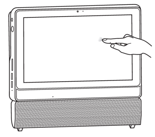
How to use the Touch Panel
The touch of your finger replaces the input devices and is all you need to operate the P20U.