P90U
How can I install an LTE module in a P90U?
Introduction
Shuttle does not offer an LTE kit for the P90U as standard. Such components are to be purchased by the customer.
In order to equip the Shuttle XPC all-in-one P90U (19.5“) with an LTE mobile network function, the following components are required:
LTE Stick (USB) with connectors for external antennas, for example:
- HUAWEI MS2372h-153 (EMEA/Africa)
- HUAWEI MS2372h-517 (North/Latin America)
- HUAWEI MS2372h-607 (Asia)


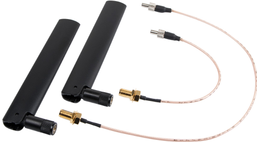
Two external LTE antennas
- With SMA connector (male)
Two antenna cables
- Connector for the LTE module: CRC9 (TS-5)
- Connector for the antenna: SMA (female)
- Cable length for P90U: 14 and 38 cm
Installation
Due to safety reasons, please turn off your computer completely first and unplug it from the power supply.
Please install with reference to the following steps:
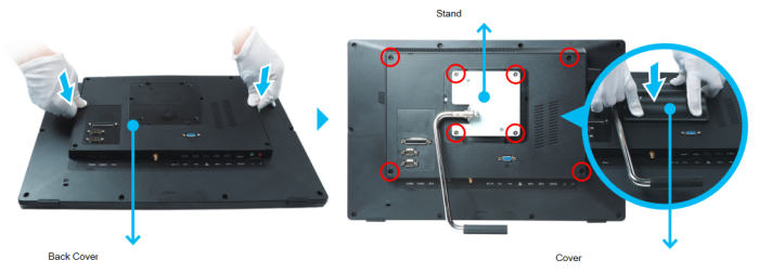
- Please remove the cover from the back of the P90U first, undo four screws of the stand mount and remove the stand.
- Unscrew four screws of the back cover and remove it.
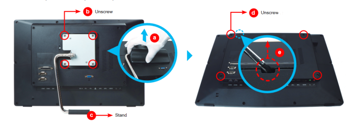
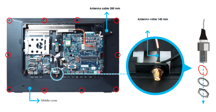
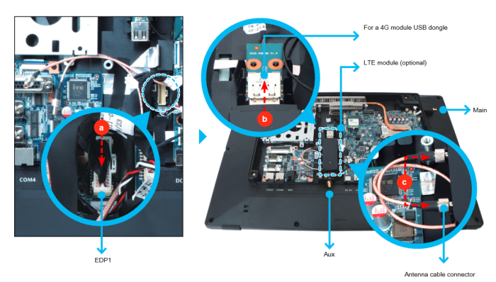
- Push the clip inward to unlock the eDP cable connector for removal. Unscrew ten screws of the middle cover and remove it. Remove the two antenna covers from both sides of the chassis (see pictures d, e).
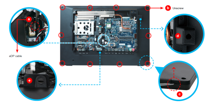
- Take out the two antenna cable connectors and remove the locks.

- First unscrew the two screws of the speaker to remove it (a). Lead the connector of the 380 mm antenna cable from the inside through the appropriate opening on the side of the chassis (b). Refasten the speaker with the two screws and route the antenna cable to the other side of chassis ©. Use the lock to affix the antenna from the outside (d).

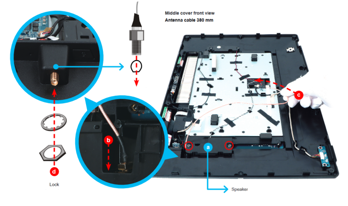
- Replace the middle cover and refasten the 10 screws. As shown, lead the connector of the 140 mm antenna cable from the inside through the appropriate opening on the side of the chassis and use the lock to affix the antenna from the outside.
- Reconnect the eDP cable to “EDP1”, then install the LTE module (optional) and connect the two antenna cable connectors to the LTE module (Main/Aux).
- Replace the back cover. Refasten the stand and the back cover with eight screws. Replace the cover.
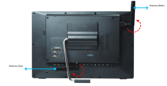
- Screw the antennas into position as pictured. Make sure they are aligned vertically to achieve the best possible signal reception.
Make sure the two antennas are aligned in the correct direction.
- Review the following BIOS setting to make sure that the LTE module is recognised correctly:
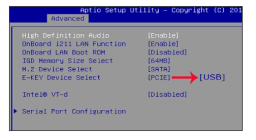
Advanced - Onboard Device Configuration - E-Key Device Select = USB