DS77U
DisplayPort restrictions of the DS77 Series
The DS77U Series can be used with up to three displays simultaneously. Due to the design of the Intel chipset, please be aware of the following restrictions when setting up your monitor.
- The DisplayPort (DP) has no audio function. Please use HDMI for displays/TVs with integrated speakers.
- Intel Collage Mode is not available. Please use a native 4K display. Older monitors using Collage Mode are not supported.
- PASSIVE adapters/cables cannot be used (e.g. DP→HDMI or DP→DVI). Please use a native DP connection or an ACTIVE adapter.
- HotPlug is not supported. Please restart the system for the display to be detected.
Note: In a 3-display setup, the DP output will show no picture while booting in BIOS mode. It will be activated once the OS has loaded the display driver.
Quick Installation Guide
Begin Installation
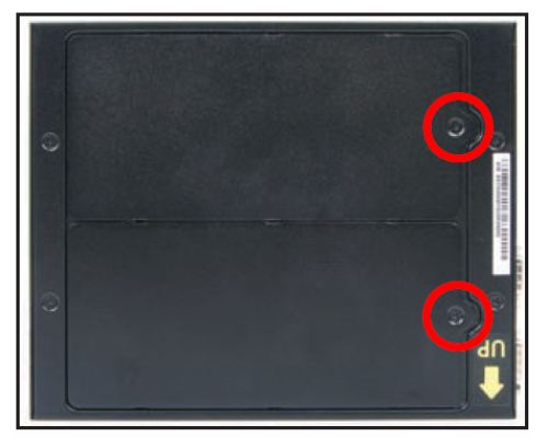
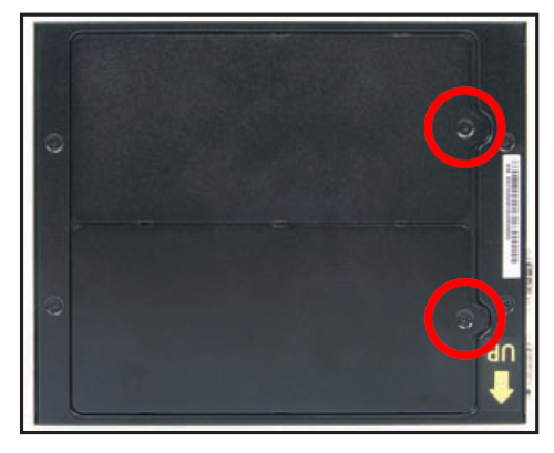
For safety reasons, please ensure that the power cord is disconnected before opening the case.
- Unscrew two screws of the chassis cover.
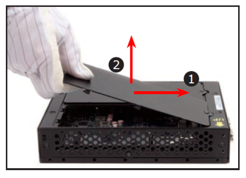
- Slide the cover forward and upward.
Memory Module Installation
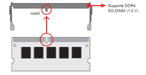
This mainboard does only support 1.2 V DDR4 SO-DIMM memory modules.
- Locate the SO-DIMM slots on the mainboard.
- Align the notch of the memory module with the one of the memory slot.
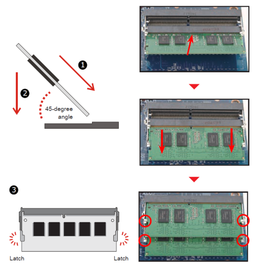
- Gently insert the module into the slot in a 45-degree angle.
- Carefully push down the memory module until it snaps into the locking mechanism.
- Repeat above steps to install additional memory modules, if desired.
Mass Storage Installation
2.5" HDD/SSD drive
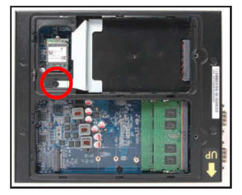
- Separate the rack from the chassis by undoing one screw.
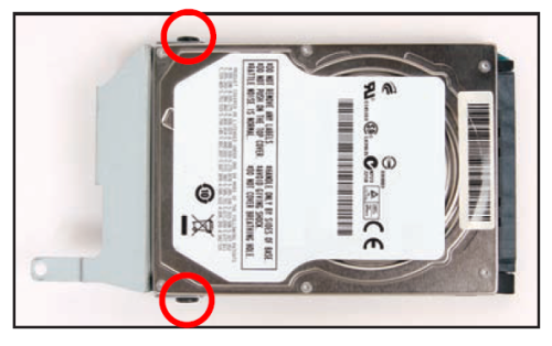
- Place the HDD or SSD in the rack and secure with two screws, one on each side.
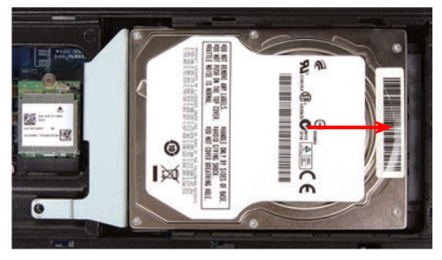
- Place the HDD or SSD in the drive bay and push it gently to the right until it clicks into place.
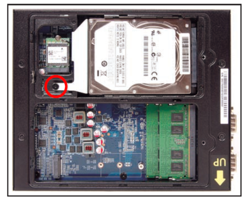
- Refasten the screws.
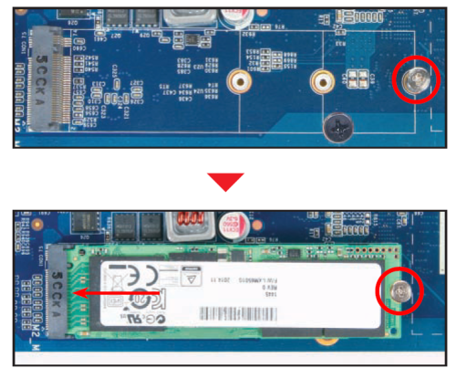
M.2 SSD module
- As shown, unfasten the screw first.
- Install the M.2 card into its slot and secure with the mentioned screw.
Complete
- Replace the covers and refasten the screws.
- Complete
Please press the “Del” key while booting to enter BIOS. Here, please load the optimised BIOS settings.
Jumper settings and pinout
COM Port 1
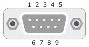
| COM1 (RS232) | |||
|---|---|---|---|
| Pin | Signal Name | Pin | Signal Name |
| 1 | DCD | 2 | RX |
| 3 | TX | 4 | DTR |
| 5 | GND | 6 | DSR |
| 7 | RTS | 8 | CTS |
| 9 | RI1- | ||
| COM1 (RS422) | |||
| Pin | Signal Name | Pin | Signal Name |
| 1 | TXD- | 2 | TXD+ |
| 3 | RXD- | 4 | RXD+ |
| 5 | GND | 6 | - |
| 7 | - | 8 | - |
| 9 | - | ||
| COM1 (RS485) | |||
| Pin | Signal Name | Pin | Signal Name |
| 1 | Data- | 2 | Data+ |
| 3 | - | 4 | - |
| 5 | GND | 6 | - |
| 7 | -8 | - | |
| 9 | - | ||
COM 1 & COM 2 Power Switch
COM PORT Pin 9 “Ring Indicator” (RI) configuration
| JP1 | |||
|---|---|---|---|
| COM1 (pin 9) | COM2 (pin 9) | ||
| Short Pin | Function | Short Pin | Function |
| 1-2 (Default) | RI1 | 3-4 (Default) | RI2 |
| 5-7 | +5V | 6-8 | +5V |
| 7-9 | +12V | 8-10 | +12V |
AC Back Auto Power ON
| JP9 | |
|---|---|
| Pin | AC Back auto Power ON function |
| Short 1-2 | Disable (Default) |
| Open | Enable |
External Power SW & Clear CMOS
| SW2 | |
|---|---|
| Pin | Signal Name |
| 1 | PWRSW |
| 2 | +5V |
| 3 | GND |
| 4 | RTC_RST# |
Operating Position
Please make sure to use either the supplied feet or the VESA mount.