This is an old revision of the document!
SH310R4
Quick Installation Guide
Begin Installation
Due to safety reasons, please ensure that the power cord is disconnected before opening the case.
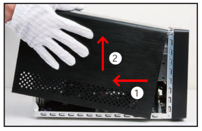
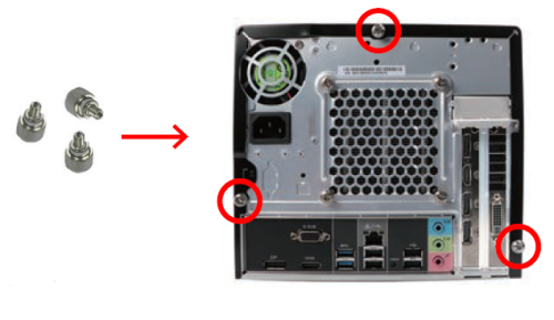
- Unscrew 3 thumbscrews of the chassis cover.
- Slide the cover backwards and upwards.
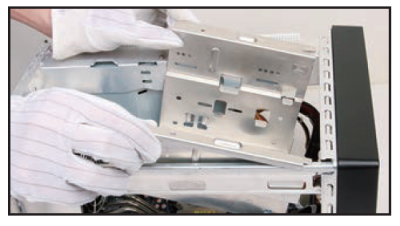
- Unfasten the rack mount screws and remove the rack.
CPU and Heatpipe Installation
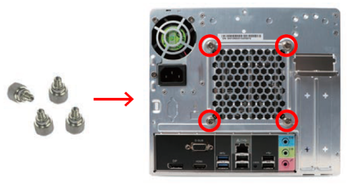
- Unfasten the Heatpipe fan thumbscrews on the back of the chassis.
- Unfasten the four Heatpipe module attachment screws and unplug the fan connector.
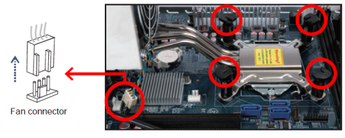
- Remove the Heatpipe module from the chassis and put it aside.
This 1151-pin socket is easily damaged and pins bend quickly. Always use extreme care when installing a CPU and limit the number of times that you remove or change the CPU. Before installing the CPU, make sure to turn off the computer and unplug the power cord from the power outlet to prevent damage of the CPU.
→ Follow the steps below to correctly install the CPU into the motherboard CPU socket. - First unlock and raise the socket lever.

- Tear off the protective membrane from the metal load plate. Lift the metal load plate off the CPU socket.
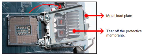
DO NOT touch socket contacts. To protect the CPU socket, always replace the protective socket cover when the CPU is not installed.
- Please orientate the CPU correctly and align the CPU notches with the socket alignment keys. Make sure the CPU sits perfectly horizontal, then push it gently into the socket.
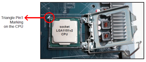
Please be aware of the CPU orientation, DO NOT force the CPU into the socket to avoid bending of pins and damage of CPU!
- Close the metal load plate, lower the CPU socket lever and lock in place.
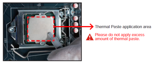
- Spread thermal paste evenly on the CPU surface.
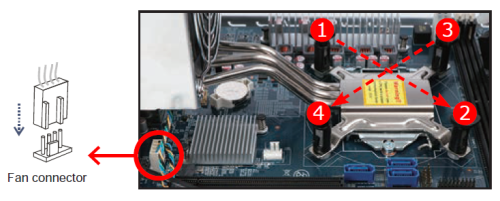
- Screw the Heatpipe module to the mainboard. Note to press down on the opposite diagonal corner while tightening each screw.
- Connect the fan connector.
- Fasten the Smart Fan to the chassis with the four thumbscrews.
Memory Module Installation
Guidelines for Memory Configuration
Before installing DIMMs, read and follow these guidelines for memory configuration:
Make sure that the motherboard supports the memory. It is recommended that memory of the same capacity, brand, speed, and chips are used. (Go to Shuttle’s website for the latest memory support list.) Memory modules have a foolproof design. A memory module can be installed in only one direction. If you are unable to insert the memory, switch direction.
Installing memory modules
DDR4 and DDR3/DDR2 DIMMs are not compatible to each other or other DDR DIMMs.
Be sure to install DDR4 DIMMs on this motherboard only. Follow the steps below to correctly install your memory modules in the memory sockets.
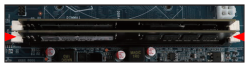
- Unlock the DIMM latch.
- Align the memory module's cutout with the DIMM slot notch. Slide the memory module into the DIMM slot.
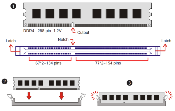
- Check if the latches are closed and if all memory modules are firmly installed.
Repeat the above steps to install additional memory modules, if required.
Component Installation
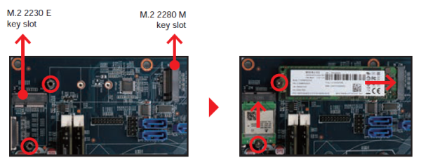
- Please proceed as shown in the illustration, and locate the M.2 key slot on the mainboard.
- Install the M.2 device into the M.2 slot and secure with a screw.
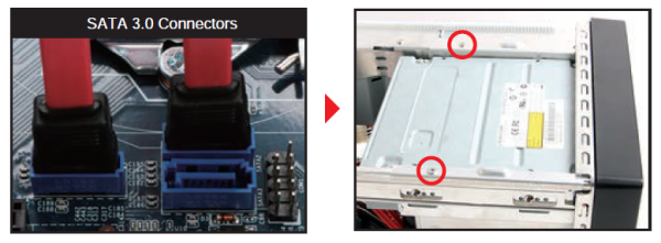
Installation of Drives
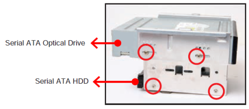
- Loosen the purse lock and separate the Serial ATA and power cables.
- Place the HDD and optical drive in the rack and secure with screws from the side.
- Connect the Serial ATA Cable to the motherboard.
- Place the rack in the chassis and refasten the rack.
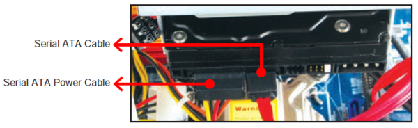
- Connect the Serial ATA and power cables to the HDD.
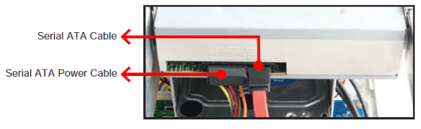
- Connect the Serial ATA and power cables to the optical drive.
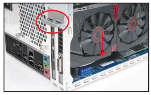
Installation of Expansion Cards
- Unfasten the expansion slot bracket screws. Remove the back panel bracket and put it aside.
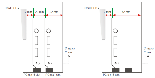
The maximum size acceptable for display cards is 273 mm x 98 mm x 38 mm.
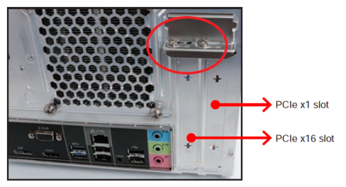
- Install the PCIe x1 / PCIe x16 card into the PCIe x1 / PCIe x16 slots.
- Secure the bracket.
Complete
- Replace the cover and refasten the thumbscrews.
- Complete.
Please press the
Delkey while booting to enter BIOS. Here, please load the optimised BIOS settings.
Jumper settings and pinout
Front audio header (JP1)
1=MIC_L
2=AGND
3=MIC_R
4=Front_Detect
5=HP_R
6=Mic_detect
7=Sense_B
8=NULL
9=HP_L
10=HP_Detect
Fan connectors (FAN1, FAN2)
1=GND
2=+12V
3=SPEED_SENSE
4=PWM_CTRL
COM header (COM1)
1=DCD
2=RXD
3=TXD
4=DTR
5=GND
6=DSR
7=RTS
8=CTS
9=-XRI1
10=NULL
LPC header (LPC1)
1=+12V
2=VCC
3=5V_DUAL
4=SERIRQ
5=LPC24M_1
6=LPC24M_2
7=SIORST-
8=LFRAME
9=LAD3
10=LAD2
11=-12V
12=3VSB
13=NA
14=LDRQ0-
15=PCH_PME-
16=LAD1
17=LAD0
18=VCC3
19=GND
20=NULL
Front USB 3.1 Gen 1 header (JP2)
1=USB30_PWR2
2=USB30_PWR2
3=USB30_PWR2
4=USB30_PWR2
5=USB3_1_RX_N
6=USB3_1_RX_P
7=GND
8=GND
9=USB3_1_TX_N
10=USB3_1_TX_P
11=GND
12=GND
13=USB2_1_N
14=USB2_1_P
15=USB30_PWR2
16=USB30_PWR2
17=USB30_PWR2
18=USB30_PWR2
19=USB3_2_RX_N
20=USB3_2_RX_P
21=GND
22=GND
23=USB3_2_TX_N
24=USB3_2_TX_P
25=GND
26=GND
27=USB2_2_N
28=USB2_2_P
29=GND
30=GND
Power switch & LED header (JP3)
1=+HD_LED
2=PWR_LED
3=-HD_LED
4=GND
5=RST_SW-
6=PWR_SW
7=GND
8=GND
9=NA
10=NULL
USB 2.0 connector (CN12)
1=GND
2=USB2P
3=USB2N
4=5V_DUAL